Disadvantages of air cooling power modules – Tech News 2403

Preface
Disadvantages of air cooling power modules
Although the market share is currently high, the disadvantages of air cooling power modules are also quite evident. Next, I will introduce to you the principles and pros and cons of air-cooled power modules.

Air cooling power modules
The principle of air cooling
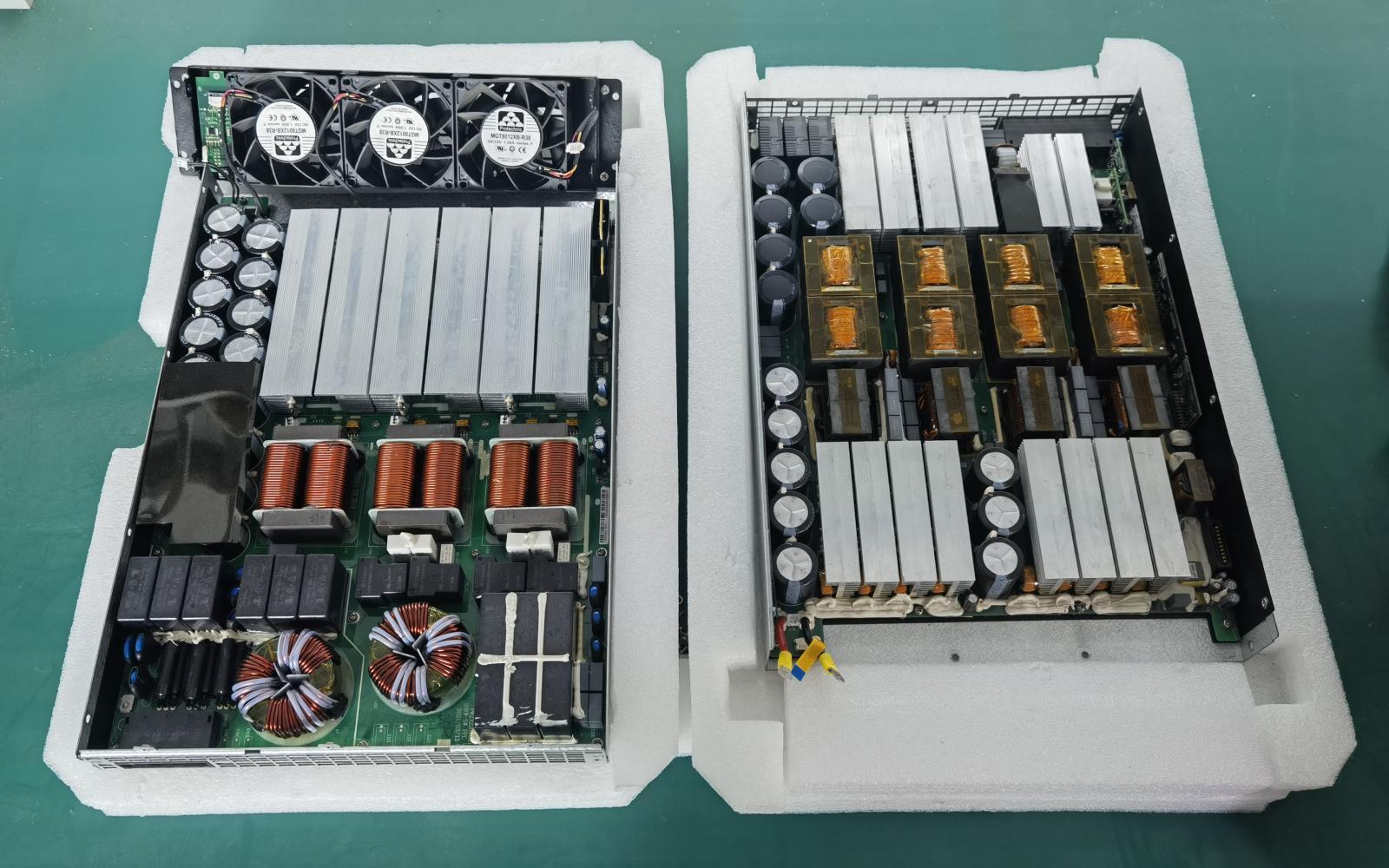
Currently, the mainstream charging module products on the market are direct airflow air-cooled modules. In traditional air-cooled modules, air is drawn in from the front panel and expelled from the rear of the module to carry away heat generated by the radiator and heating elements.
Environmental factor
Due to the outdoor environment of EV chargers, there is a mixture of dust, salt spray, and moisture in the air that accumulates on the surface of internal components. The accumulation of dust inside can result in poor insulation, reduced heat dissipation, lower charging efficiency, and decreased equipment lifespan. Additionally, during rainy or humid seasons, water absorbed by the accumulated dust may lead to mold growth and corrosion of components, causing module and equipment short-circuit faults.
Protection technology solutions
Traditional three-proof material double-sided spray coating
Traditional double-sided three-proof technology is limited by the issue of three-proof nozzles, which hinders the effective application of three-proof coatings in physically constrained spaces such as the bottom of heat sinks. It also fails to form a protective layer at the tip of component soldering legs or sharp corners. Although remedial measures like manual spraying can be employed, achieving 100% protection is not possible. Additionally, these three-proof coatings have poor weather resistance and may experience localized peeling issues after three years or more.
Traditional three-proofing and glue filling
The back of the printed circuit board adopts a traditional three-proof coating scheme, with adhesive pads for protection at the air inlet and outlet. The front of the printed circuit board uses a glue filling scheme. Although this solution can partially prevent dust particles on the back of the printed circuit board, it cannot provide 100% protection. It also has poorer performance in preventing condensation caused by gases. Additionally, due to the obstruction of airflow on the back of the printed circuit board, this solution has relatively poor heat dissipation effectiveness.
UV three-proof and glue filling
The back of the printed circuit board is coated with UV. In fact, in terms of protection effectiveness for through-hole components on the back of the printed circuit board, this approach is similar to traditional three-proofing methods. According to field dust accumulation tests conducted under simulated harsh conditions over a period of 5 years, there is little difference in test results whether using three-proofing or UV coating as the treatment method.
Single-sided / overall gluing
There are some issues with these two solutions. The former does not achieve full coverage on the surface of the printed circuit board (PCB), and the PCB material itself is water-absorbent, allowing moisture to enter between layers and compromise insulation. The latter requires a large amount of adhesive, resulting in higher material costs, and it cannot effectively verify if there are any voids at the bottom of the PCB. Additionally, sealing off the bottom and blocking heat dissipation channels reduces the PCB’s own ability to dissipate heat.


0 Comments